Showing posts with label CCNA Prep. Show all posts

Thursday, January 7, 2010

Maximum length of various cable types


Interestingly, the 5 and 2 in the names 10BASE5 and 10BASE2 represent the maximum cable length.
UTP cable needs two pairs of wires for 10BASE-T and 100BASE-TX and four pairs of wires for 1000BASE-T. This section focuses on the pinouts for two-pair wiring, with four-pair wiring covered next.
Also, Gigabit Ethernet transmits and receives on each of the four wire pairs simultaneously.


Multicast addresses: Multicast addresses are used to allow a subset of devices on a LAN to communicate. When IP multicasts over an Ethernet, the multicast MAC addresses used by IP follow this format: 0100.5exx.xxxx, where any value can be used in the last half of the address.

Sunday, January 3, 2010

STP, RSTP and so on.

STP (IEEE 802.1d)

STP defines messages called bridge protocol data units (BPDU), which bridges and switches use to exchange information with each other. The most common message, called a Hello BPDU, lists the sending switch’s bridge ID. By listing its own unique bridge ID, switches can tell the difference between BPDUs sent by different switches. This message also lists the bridge ID of the current root switch.
Hello interval 2 seconds.

Electing the Root Switch
Switches elect a root switch based on the bridge IDs in the BPDUs. The root switch is the switch with the lowest numeric value for the bridge ID. 
BID = Priority + MAC-address
After the election is complete, only the root switch continues to originate STP Hello BPDU messages. The other switches receive the Hellos, update the sender’s BID field (and costtoreach-the-root field), and forward the Hellos out other interfaces.

Choosing Each Switch’s Root Port
The second part of the STP process occurs when each nonroot switch chooses its one and only root port. A switch’s root port (RP) is its interface through which it has the least STP cost to reach the root switch.


Choosing the Designated Port on Each LAN Segment
STP’s final step to choose the STP topology is to choose the designated port on each LAN segment. The designated port on each LAN segment is the switch port that advertises the lowest-cost Hello onto a LAN segment. When a nonroot switch forwards a Hello, the nonroot switch sets the cost field in the Hello to that switch’s cost to reach the root. In effect, the switch with the lower cost to reach the root, among all switches connected to a segment, becomes the DP on that segment.


When I need to choose the designated port, I should calculate the cost to reach the root bridge based not on the cost of port(!!!), but based on the LINK cost!!!
Like If 2 switch connects to each other one with FastEthernet port and the other one with GigabitEthernet port, then from the perspective of any switch the link will be 19, not 4!!!

Ethernet Speed              Cost
10Mbps                          100
100Mbps                         19
1Gbps                               4
10Gbps                             2

For switch interfaces connected to hosts or routers, which do not use STP, the switch will still forward Hellos onto those interfaces

The following list summarizes the steady-state operation when nothing is currently changing in the STP topology:
1.The root creates and sends a Hello BPDU, with a cost of 0, out all its working interfaces (those in a   Forwarding State).
2. The nonroot switches receive the Hello on their root ports. After changing the Hello to list their own bridge ID as the sender’s BID, and listing that switch’s root cost, the switch forwards the Hello out all designated ports.
3. Steps 1 and 2 repeat until something changes.

Each switch relies on these periodic received Hellos from the root as a way to know that its path to the root is still working. When a switch ceases to receive the Hellos, something has failed, so the switch reacts and starts the process of changing the spanning-tree topology. Note that all switches use the timers as dictated by the root switch, which the root lists in its periodic Hello BPDU messages.


Optional STP features

PortFast
PortFast allows a switch to immediately place a port in Forwarding State when the port becomes physically active, bypassing any choices about the STP topology and bypassing the Listening and Learning States.

STP Security
The Cisco BPDU Guard feature disabling a port if any BPDUs are received on the port.

The Root Guard feature allows another switch to be connected to the interface, and participate in STP by sending and receiving BPDUs. However, when the switch interface with Root Guard enabled receives a superior BPDU from the neighboring switch—a BPDU that has a lower/better bridge ID—the switch with Root Guard reacts. Not only does the switch ignore the superior BPDU, but the switch also disables the interface, not sending or receiving frames, as long as the superior BPDUs keep arriving. If the superior BPDUs stop arriving, the switch can start using the interface again.

Rapid STP (IEEE 802.1w)
RSTP (802.1w) works just like STP (802.1d) in several ways:
■ It elects the root switch using the same parameters and tiebreakers.
■ It elects the root port on nonroot switches with the same rules.
■ It elects designated ports on each LAN segment with the same rules.
■ It places each port in either Forwarding or Blocking State, although RSTP calls the Blocking State the Discarding State.


RSTP can be deployed alongside traditional 802.1d STP switches, with RSTP features working in switches that support it, and traditional 802.1d STP features working in the switches that support only STP.

RSTP only has to wait 3*Hello (default 6 seconds). Additionally, RSTP eliminates the forward delay (default 15 seconds) time in both Listening and Learning States.


The IEEE did not attempt to make RSTP work in networks that use shared hubs, and RSTP would not improve convergence in the network on the right. RSTP calls Ethernet connections between switches links and calls Ethernet connections to end-user devices edges. RSTP does not distinguish between point-to-point and shared types for edge connections.

RSTP Port States

Discarding means that the port does not forward frames, process received frames, or learn MAC addresses, but it does listen for BPDUs. In short, it acts just like the STP Blocking State. RSTP uses an interim Learning State when moving an interface from a Discarding State to Forwarding State. However, RSTP needs to use Learning State for only a short time.

RSTP Port Roles
Both STP (802.1d) and RSTP (802.1w) use the concepts of port states and port roles. The STP process determines the role of each interface. For example, STP determines which interfaces are currently in the role of a root port or designated port. Then, STP determines the stable port state to use for interfaces in certain roles: the Forwarding State for ports in the RP or DP roles, and the Blocking State for ports in other roles.

The RSTP alternate port role identifies a switch’s best alternative to its current RP.
The other new RSTP port type, backup port, applies only when a single switch has two links
to the same segment (collision domain) .


 RSTP Convergence

The RSTP Spanning Tree Algorithm (STA) works somewhat differently than its olderpredecessor. For example, under stable conditions, every switch independently generates and sends Hello BPDUs, rather than only changing and forwarding the Hellos sent by the root switch. However, under stable conditions, the end results are the same: A switch that continues to hear the same Hellos, with the same cost and root switch BID listed, leaves the STP topology as is.

The main changes with RSTP’s version of the STA occur when changes occur in the
network. RSTP acts differently on some interfaces based on RSTP’s characterization of the
interface based on what is connected to the interface.

Edge-Type Behavior and PortFast
RSTP improves convergence for edge-type connections by immediately placing the port in Forwarding State when the link is physically active. In effect, RSTP treats these ports just like the Cisco-proprietary PortFast feature.
Link-Type Shared
RSTP doesn’t do anything differently from STP on link-type shared links.
Link-Type Point-to-Point
RSTP improves convergence over full-duplex links between switches—the links that RSTP calls “link-type point-to-point.” The first improvement made by RSTP over these types of links relates to how STP uses MaxAge. STP requires that a switch that no longer receives root BPDUs in its root port must wait for MaxAge seconds before starting convergence. MaxAge defaults to 20 seconds. RSTP recognizes the loss of the path to the root bridge, through the root port, in 3 times the Hello timer, or 6 seconds with a default Hello timer value of 2 seconds.


On Cisco switches, the STP cost is based on the actual speed of the interface, so if an interface negotiates to use a lower speed, the default STP cost reflects that lower speed per Table 2-6. If the interface negotiates to use a different speed, the switch dynamically changes the STP port cost as well.

Determining the Root Port on Nonroot Switches
Step 1 Determine all possible paths over which a frame, sent by the nonroot switch, can reach the root switch.
Step 2 For each possible path in Step 1, add the costs of all outgoing interfaces in that path.
Step 3 The lowest cost found is the cost to reach the root, and the outgoing interface is that switch’s RP.
Step 4 If the cost ties, use the port priority tiebreaker, and if that ties, use the lowest port number tiebreaker. 

Determining the Designated Port on Each LAN Segment
Step 1 For switches connected to the same LAN segment, the switch with the lowest cost to reach the root is the DP on that segment.
Step 2 In case of a tie, among the switches that tied on cost, the switch with the lowest BID becomes the DP.


Friday, January 1, 2010

IPv6

128-bit long address.
FFFF:0000:0000:0000:0000:0000:0000:FFFF  - my observation: each letter in an address is /4 for prefix length. Like(network part in bold):
  • F000::1/4
  • FF00::1/8, etc.

2000::/3 - stands for global unicast address prefix.
FD00::/8 - unique local unicast address prefix.


FE80::/10 - link local unicast address prefix. Using for functions, which don't need to leave the subnet. No specific configuration is required, because a host forms these addresses by using the first 10 bits of hex FE80 (binary 1111111010), 54 more binary 0s, and the last 64 bits being the host’s EUI-64 format interface ID. For example, hosts use this address for NDP RS messages.


FF00::/8 - stands for multicast address prefix.
FF02::/16 - multicast that stay on the local link.
::1 - represents loopback address.
:: - reserver address which can be used when host doesn't know his IPv6 address and is trying to discover it.
FF02::1:2 - reserved for hosts to be used when searching for unknown DHCP server.


Interface ID and EUI-64 Format

MAC addresses are 6 bytes (48 bits) in length, so for a host to automatically decide on a value to use in the 8-byte (64-bit) interface ID field, IPv6 cannot simply copy just the MAC address. To complete the 64-bit interface ID, IPv6 fills in 2 more bytes. Interestingly, to do so, IPv6 separates the MAC address into two 3-byte halves, and inserts hex FFFE in between the halves, to form the interface ID field, as well as setting 1 special bit to binary 1. EUI-64 format requires setting the seventh bit in the first byte of MAC-address to binary 1. The underlying reason is that Ethernet MAC addresses are listed with the low-order bits of each byte on the left, and the high-order bits on the right.


Dynamic IPv6 address autoconfiguration.

IPv6 supports two methods of dynamic configuration of IPv6 addresses. One uses a stateful DHCPv6 server and another uses stateless autoconfiguration.

Stateless autoconfiguration uses two NDP messages, namely router solicitation (RS) and router advertisement (RA) messages, to discover the IPv6 prefix used on a LAN.
The host sends the RS message as an IPv6 multicast message, asking all routers to respond to the questions “What IPv6 prefix(s) is used on this subnet?” and “What is the IPv6 address(s) of any default routers on this subnet?” IPv6 does not use broadcasts.


IPv6 Transition Options

Tuesday, December 22, 2009

ACL + Wildcards

Wildcards don't have to be consecutive of binary 1s or 0s. Wildcard could be 0.255.0.0 or 0.0.66.0 etc. Routers examine each bit in IP address and compare it to wildcard. When router checks each wildcard bit, the logic is following: if bit equal to 0 than IP address' corresponding bit should match and if bit equal to 1 than IP address' bit doesn't have to match.
To get a wildcard from a subnet mask, we need to substract mask from 255.255.255.255.
    255.255.255.255
−  255.255.252. 0
      0.    0.    3.  255

The number range for standart ACLs is 1 to 99 and 1300 to 1999.
Standard ACLs should be placed near to the destination of the packets so that it does not unintentionally discard packets that should not be discarded.

The extended access-list command uses numbers between 100–199 and 2000–2699.
Extended ACLs should be placed as close as possible to the source of the packets.

Routse summarization

For summarize the routes first I need to look at the least subnet.
Then I have to decide which block size to use based on whole range of subnets.
For example:
10.2.1.0/24
10.2.2.0/24
10.2.3.0/24
10.2.4.0/24
Can't use block size of 4 because then it's only 10.2.0.0 - 1.2.3.255  (10.2.4.0 won't be included).
I need to use block size - 8 - then final mask will be 255.255.255.248
10.2.0.0  255.255.255.248 - summary route

Example 2:
  • 172.1.4.128/25
  • 172.1.7.0/24
  • 172.1.6.0/24
  • 172.1.5.0/24
  • 172.1.4.0/25
Do you see an octet that looks interesting to you? I do. It’s the third octet. 4, 5, 6, 7, and yes, it’s a block size of 4. So you can summarize 172.1.4.0 using a mask of 255.255.252.0, which means you will use a block size of 4 in the third octet. The IP addresses forwarded with this summary are 172.1.4.1 through 172.1.7.255.

Monday, December 7, 2009

Internal components + Boot sequence + Recovering Password

The Internal Components of a Cisco Router


Bootstrap Stored in the microcode of the ROM, the bootstrap is used to bring a router up during initialization. It will boot the router and then load the IOS.
POST (power-on self-test) Stored in the microcode of the ROM, the POST is used to check the basic functionality of the router hardware and determines which interfaces are present.
ROM monitor Stored in the microcode of the ROM, the ROM monitor is used for manufacturing, testing, and troubleshooting.
Mini-IOS Called the RXBOOT or bootloader by Cisco, the mini-IOS is a small IOS in ROM that can be used to bring up an interface and load a Cisco IOS into flash memory. The mini-IOS can also perform a few other maintenance operations.
RAM (random access memory) Used to hold packet buffers, ARP cache, routing tables, and also the software and data structures that allow the router to function.
Running-config is stored in RAM, and most routers expand the IOS from flash into RAM upon boot.
ROM (read-only memory) Used to start and maintain the router. Holds the POST and the bootstrap program, as well as the mini-IOS.
Flash memory Stores the Cisco IOS by default. Flash memory is not erased when the router is reloaded. It is EEPROM (electronically erasable programmable read-only memory) created by Intel.
NVRAM (nonvolatile RAM) Used to hold the router and switch configuration. NVRAM is not erased when the router or switch is reloaded. Does not store an IOS. The configuration register is stored in NVRAM.
Configuration register Used to control how the router boots up. This value can be found as the last line of the show version command output and by default is set to 0x2102, which tells the router to load the IOS from flash memory as well as to load the configuration from NVRAM.

The default order of an IOS loading from a router is Flash, TFTP server, then ROM.

The Router Boot Sequence


1. The router performs a POST. The POST is stored in and run from ROM (read-only memory).
2. The bootstrap then looks for and loads the Cisco IOS software. The bootstrap is a program in ROM that is used to execute programs. The bootstrap program is responsible for finding where each IOS program is located and then loading the file. By default, the IOS software is loaded from flash memory in all Cisco routers.
3. The IOS software looks for a valid configuration file stored in NVRAM. This file is called startup-config and is only there if an administrator copies the running-config file into NVRAM. (As you already know, the new ISR routers have a small startupconfig file preloaded.)
4. If a startup-config file is in NVRAM, the router will copy this file and place it in RAM and call the file running-config. The router will use this file to run the router. The router should now be operational. If a startup-config file is not in NVRAM, the router will broadcast out any interface that detects carrier detect (CD) for a TFTP host looking for a configuration, and when that fails (typically it will fail—most people won’t even realize the router has attempted this process), it will start the setup mode configuration process.

Recovering Passwords
  1. Boot the router and interrupt the boot sequence by performing a break, which will take the router into ROM monitor mode.
  2. Change the configuration register to turn on bit 6 (with the value 0x2142).
  3. Reload the router.
  4. Enter privileged mode.
  5. Copy the startup-config file to running-config.
  6. Change the password.
  7. Reset the configuration register to the default value.
  8. Save the router configuration.
  9. Reload the router (optional).

Wednesday, December 2, 2009

Tuesday, December 1, 2009

IP addressing

IPv4
  • Network Address Range: Class A
0xxxxxxx
00000000 = 0
01111111 = 127
  • Network Address Range: Class B
In a Class B network, the RFCs state that the first bit of the first byte must always be turned on but the second bit must always be turned off.
10000000 = 128
10111111 = 191
  • Network Address Range: Class C
11000000 = 192
11011111 = 223
  • Network Address Range: Class D
11100000 = 224
11101111 = 239

Reserved IP Address Space
Address Class                         Reserved Address Space
Class A                           10.0.0.0 through 10.255.255.255
Class B                           172.16.0.0 through 172.31.255.255
Class C                           192.168.0.0 through 192.168.255.255

IP Header

Possible Protocols Found in the Protocol Field of an IP Header
      Protocol                   Protocol Number
  • ICMP 1
  • IP in IP (tunneling) 4
  • IGRP 9
  • EIGRP 88
  • OSPF 89
  • IPv6 41
  • GRE 47
  • Layer 2 tunnel (L2TP) 115

RFC

  • RFC 768 is UDP
  • RFC 3232 defines well-known ports
  • RFC 791 discuss IP 
  • RFC 1256 is an annex to ICMP

OSI layers remarks

Serial interrface = V.35 physical int
Transport layer:

TCP creates a virtual circuit!
UDP doesn’t create a virtual circuit!
And both check FCS field for CRC errors.

The types of flow control are buffering, windowing, and congestion avoidance.

Windows are used to control the amount of outstanding, unacknowledged data segments.

Data-link layer standards:


Media Access Control (MAC) 802.3 Defines how packets are placed on the media. Contention media access is “first come/first served” access where everyone shares the same bandwidth— hence the name. Physical addressing is defined here, as well as logical topologies. What’s a logical topology? It’s the signal path through a physical topology. Line discipline, error notification (not correction), ordered delivery of frames, and optional flow control can also be used at this sublayer.
Logical Link Control (LLC) 802.2 Responsible for identifying Network layer protocols and then encapsulating them. An LLC header tells the Data Link layer what to do with a packet once a frame is received. It works like this: A host will receive a frame and look in the LLC header to find out where the packet is destined—say, the IP protocol at the Network layer. The LLC can also provide flow control and sequencing of control bits.


The switches and bridges I talked about near the beginning of the chapter both work at the Data Link layer and filter the network using hardware (MAC) addresses.

MAC address is a 48-bit long.

Encapsulating a frame within a different type of frame is called tunneling.

Hubs at the Physical Layer.

The Physical layer specifies the electrical, mechanical, procedural, and functional requirements for activating, maintaining, and deactivating a physical link between end systems. This layer is also where you identify the interface between the data terminal equipment (DTE) and the data communication equipment (DCE). The DCE is usually located at the service provider, while the DTE is the attached device. The services available to the DTE are most often accessed via a modem or channel service unit/data service unit (CSU/DSU).

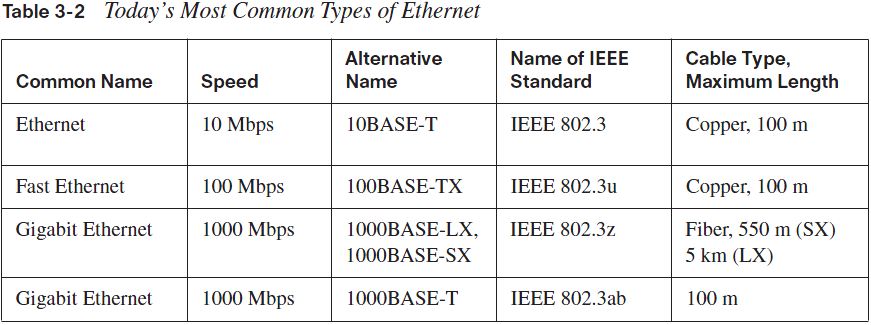
The IEEE extended the 802.3 Committee to two new committees known as 802.3u (Fast Ethernet) and 802.3ab (Gigabit Ethernet on category 5) and then finally 802.3ae (10Gbps over fiber and coax).


Attenuation is the loss of signal strength as it travels the length of a cable and is measured in decibels(dB).
Crosstalk is the unwanted signal interference from adjacent pairs in the cable.


10Base2 10Mbps, baseband technology, up to 185 meters in length. Known as thinnet and can support up to 30 workstations on a single segment. Uses a physical and logical bus with AUI connectors. Base means baseband technology (which is a signaling method for communication on the network), and the 2 means almost 200 meters. 10Base2 Ethernet cards use BNC (British Naval Connector, Bayonet Neill Concelman, or Bayonet Nut Connector) and T-connectors to connect to a network.
10Base5 10Mbps, baseband technology, up to 500 meters in length. Known as thicknet. Uses a physical and logical bus with AUI connectors. Up to 2,500 meters with repeaters and 1,024 users for all segments.
10BaseT 10Mbps using category 3 UTP wiring up to 100 meters. Unlike with the 10Base2 and 10Base5 networks, each device must connect into a hub or switch, and you can have only one host per segment or wire. Uses an RJ45 connector (8-pin modular connector) with a physical star topology and a logical bus.
100BaseTX (IEEE 802.3u) EIA/TIA category 5, 6, or 7 UTP two-pair wiring. One user per segment; up to 100 meters long. It uses an RJ45 connector with a physical star topology and a logical bus.
100BaseFX (IEEE 802.3u) Uses fiber cabling 62.5/125-micron multimode fiber. Point-to-point topology; up to 412 meters long. It uses an ST or SC connector, which are mediainterface connectors.
1000BaseCX (IEEE 802.3z) Copper twisted-pair called twinax (a balanced coaxial pair) that can only run up to 25 meters.
1000BaseT (IEEE 802.3ab) Category 5, four-pair UTP wiring up to 100 meters long.
1000BaseSX (IEEE 802.3z) MMF using 62.5- and 50-micron core; uses an 850 nano-meter laser and can go up to 220 meters with 62.5-micron, 550 meters with 50-micron.
1000BaseLX (IEEE 802.3z) Single-mode fiber that uses a 9-micron core and 1300 nanometer laser and can go from 3 kilometers up to 10 kilometers.

Exam essentials

Remember the possible causes of LAN traffic congestion. Too many hosts in a broadcast domain, broadcast storms, multicasting, and low bandwidth are all possible causes of LAN traffic congestion.
Understand the difference between a collision domain and a broadcast domain. Collision domain is an Ethernet term used to describe a network collection of devices in which one particular device sends a packet on a network segment, forcing every other device on that same segment to pay attention to it. On a broadcast domain, a set of all devices on a network segment hear all broadcasts sent on that segment.
Understand the difference between a hub, a bridge, a switch, and a router. Hubs create one collision domain and one broadcast domain. Bridges break up collision domains but create one large broadcast domain. They use hardware addresses to filter the network. Switches are really just multiple port bridges with more intelligence. They break up collision domains but create one large broadcast domain by default. Switches use hardware addresses to filter the network. Routers break up broadcast domains (and collision domains) and use logical addressing to filter the network.
Remember the difference between connection-oriented and connectionless network services.
Connection-oriented services use acknowledgments and flow control to create a reliable session. More overhead is used than in a connectionless network service. Connectionless services are used to send data with no acknowledgments or flow control. This is considered unreliable.
Remember the OSI layers. You must remember the seven layers of the OSI model and what function each layer provides. The Application, Presentation, and Session layers are upper layers and are responsible for communicating from a user interface to an application. The Transport layer provides segmentation, sequencing, and virtual circuits. The Network layer provides logical network addressing and routing through an internetwork. The Data Link layer provides framing and placing of data on the network medium. The Physical layer is responsible for taking 1s and 0s and encoding them into a digital signal for transmission on the network segment.
Remember the types of Ethernet cabling and when you would use them. The three types of cables that can be created from an Ethernet cable are straight-through (to connect a PC’s or a router’s Ethernet interface to a hub or switch), crossover (to connect hub to hub, hub to switch, switch to switch, or PC to PC), and rolled (for a console connection from a PC to a router or switch).
Understand how to connect a console cable from a PC to a router and start HyperTerminal.
Take a rolled cable and connect it from the COM port of the host to the console port of a router. Start HyperTerminal and set the BPS to 9600 and flow control to None.
Remember the three layers in the Cisco three-layer model. The three layers in the Cisco hierarchical model are the core, distribution, and access layers.

Remember the various configuration register commands and settings. The 0x2102 setting is the default on all Cisco routers and tells the router to look in NVRAM for the boot sequence. 0x2101 tells the router to boot from ROM, and 0x2142 tells the router to not load the startupconfig in NVRAM to provide password recovery.
Remember how to back up an IOS image. By using the privileged-mode command copy flash tftp, you can back up a file from flash memory to a TFTP (network) server.
Remember how to restore or upgrade an IOS image. By using the privileged-mode command copy tftp flash, you can restore or upgrade a file from a TFTP (network) server to flash memory.
Remember what you must complete before you back up an IOS image to a network server.
Make sure that you can access the network server, ensure that the network server has adequate space for the code image, and verify the file naming and path requirement.
Remember how to save the configuration of a router. There are a couple of ways to do this, but the most common, as well as most tested, method is copy running-config startup-config.
Remember how to erase the configuration of a router. Type the privileged-mode command erase startup-config and reload the router.
Understand when to use CDP. Cisco Discovery Protocol can be used to help you document as well as troubleshoot your network.
Remember what the output from the show cdp neighbors command shows. The show cdp neighbors command provides the following information: device ID, local interface, holdtime, capability, platform, and port ID (remote interface).
Understand how to telnet into a router and keep your connection but return to your originating console. If you telnet to a router or switch, you can end the connection by typing exit at any time. However, if you want to keep your connection to a remote device but still come back to your original router console, you can press the Ctrl+Shift+6 key combination, release it, and then press X.
Remember the command to verify your Telnet sessions. The command show sessions will provide you with information about all the sessions your router has with other routers.
Remember how to build a static host table on a router. By using the global configuration command ip host host_name ip_address, you can build a static host table on your router. You can apply multiple IP addresses against the same host entry.
Remember how to verify your host table on a router. You can verify the host table with the show hosts command.

Remember the steps to subnet in your head. Understand how IP addressing and subnetting work. First, determine your block size by using the 256-subnet mask math. Then count your
subnets and determine the broadcast address of each subnet—it is always the number right before the next subnet. Your valid hosts are the numbers between the subnet address and the broadcast address.
Understand the various block sizes. This is an important part of understanding IP addressing and subnetting. The valid block sizes are always 4, 8, 16, 32, 64, 128, etc. You can determine your block size by using the 256-subnet mask math.
Remember the four diagnostic steps. The four simple steps that Cisco recommends for troubleshooting are ping the loopback address, ping the NIC, ping the default gateway, and ping the remote device.
You must be able to find and fix an IP addressing problem. Once you go through the four troubleshooting steps that Cisco recommends, you must be able to determine the IP addressing problem by drawing out the network and finding the valid and invalid hosts addressed in your network.
Understand the troubleshooting tools that you can use from your host and a Cisco router
ping 127.0.0.1 tests your local IP stack. tracert is a Windows DOS command to track the path a packet takes through an internetwork to a destination. Cisco routers use the command traceroute, or just trace for short. Don’t confuse the Windows and Cisco commands. Although they produce the same output, they don’t work from the same prompts. ipconfig /all will display your PC network configuration from a DOS prompt, and arp -a (again from a DOS prompt) will display IP-to-MAC-address mapping on a Windows PC.

Cisco hierarchical model

The following are the three layers and their typical functions:

  1. The core layer: backbone
  2. The distribution layer: routing
  3. The access layer: switching
The Core Layer
The core layer is literally the core of the network. At the top of the hierarchy, the core layer is responsible for transporting large amounts of traffic both reliably and quickly. The only purpose of the network’s core layer is to switch traffic as fast as possible. The traffic transported acrossthe core is common to a majority of users. However, remember that user data is processed at the distribution layer, which forwards the requests to the core if needed. If there is a failure in the core, every single user can be affected. Therefore, fault tolerance at this layer is an issue. The core is likely to see large volumes of traffic, so speed and latency are driving concerns here. Given the function of the core, we can now consider some design specifics. Let’s start with some things we don’t want to do:
  • Don’t do anything to slow down traffic. This includes using access lists, routing between virtual local area networks (VLANs), and implementing packet filtering.
  • Don’t support workgroup access here.
  • Avoid expanding the core (i.e., adding routers) when the internetwork grows. If performance becomes an issue in the core, give preference to upgrades over expansion. 
Now, there are a few things that we want to do as we design the core:
  • Design the core for high reliability. Consider data-link technologies that facilitate both speed and redundancy, such as FDDI, Fast Ethernet (with redundant links), or even ATM.
  • Design with speed in mind. The core should have very little latency.
  • Select routing protocols with lower convergence times. Fast and redundant data-link connectivity is no help if your routing tables are shot!
The Distribution Layer
The distribution layer is sometimes referred to as the workgroup layer and is the communication point between the access layer and the core. The primary functions of the distribution layer are to provide routing, filtering, and WAN access and to determine how packets can access the core, if needed. The distribution layer must determine the fastest way that network service requests are handled—for example, how a file request is forwarded to a server. After the distribution layer determines the best path, it forwards the request to the core layer if necessary. The core layer then quickly transports the request to the correct service.
The distribution layer is the place to implement policies for the network. Here you can exercise considerable flexibility in defining network operation. There are several actions that generally should be done at the distribution layer:
  • Routing
  • Implementing tools (such as access lists), packet filtering, and queuing
  • Implementing security and network policies, including address translation and firewalls
  • Redistributing between routing protocols, including static routing
  • Routing between VLANs and other workgroup support functions
  • Defining broadcast and multicast domains
Things to avoid at the distribution layer are limited to those functions that exclusively
belong to one of the other layers.

The Access Layer
The access layer controls user and workgroup access to internetwork resources. The access layer is sometimes referred to as the desktop layer. The network resources most users need will be available locally. The distribution layer handles any traffic for remote services. The following are some of the functions to be included at the access layer:
  • Continued (from distribution layer) use of access control and policies
  • Creation of separate collision domains (segmentation)
  • Workgroup connectivity into the distribution layer
Technologies such as DDR and Ethernet switching are frequently seen in the access layer. Static routing (instead of dynamic routing protocols) is seen here as well. As already noted, three separate levels does not imply three separate routers. There could be fewer, or there could be more. Remember, this is a layered approach.

    Binary Math

    Binary to Decimal Memorization Chart

        Binary              Decimal

    10000000               128
    11000000               192
    11100000               224
    11110000               240
    11111000               248
    11111100               252
    11111110               254
    11111111               255

    Various show commands

    1. show cdp
    2. show cdp neighbors
      The show cdp neighbors command provides the following information: device ID, local interface, holdtime, capability, platform, and port ID (remote interface).

    3. sh cdp neighbors detail
    4. sh cdp entry *
    5. show cdp entry * protocols
      Protocol information for ap :
      IP address: 10.1.1.2
      Protocol information for R2 :
      IP address: 10.4.4.2
    6. show cdp entry * version
      Version information for ap :
      Cisco IOS Software, C1240 Software (C1240-K9W7-M), Version
      12.3(8)JEA, RELEASE SOFTWARE (fc2)
      [lines omitted]
    7. show protocols