STP (IEEE 802.1d)
STP defines messages called bridge protocol data units (BPDU), which bridges and switches use to exchange information with each other. The most common message, called a Hello BPDU, lists the sending switch’s bridge ID. By listing its own unique bridge ID, switches can tell the difference between BPDUs sent by different switches. This message also lists the bridge ID of the current root switch.
Hello interval 2 seconds.
Electing the Root Switch
Switches elect a root switch based on the bridge IDs in the BPDUs. The root switch is the switch with the lowest numeric value for the bridge ID.
Switches elect a root switch based on the bridge IDs in the BPDUs. The root switch is the switch with the lowest numeric value for the bridge ID.
BID = Priority + MAC-address
After the election is complete, only the root switch continues to originate STP Hello BPDU messages. The other switches receive the Hellos, update the sender’s BID field (and costtoreach-the-root field), and forward the Hellos out other interfaces.
Choosing Each Switch’s Root Port
The second part of the STP process occurs when each nonroot switch chooses its one and only root port. A switch’s root port (RP) is its interface through which it has the least STP cost to reach the root switch.
The second part of the STP process occurs when each nonroot switch chooses its one and only root port. A switch’s root port (RP) is its interface through which it has the least STP cost to reach the root switch.
Choosing the Designated Port on Each LAN Segment
STP’s final step to choose the STP topology is to choose the designated port on each LAN segment. The designated port on each LAN segment is the switch port that advertises the lowest-cost Hello onto a LAN segment. When a nonroot switch forwards a Hello, the nonroot switch sets the cost field in the Hello to that switch’s cost to reach the root. In effect, the switch with the lower cost to reach the root, among all switches connected to a segment, becomes the DP on that segment.
STP’s final step to choose the STP topology is to choose the designated port on each LAN segment. The designated port on each LAN segment is the switch port that advertises the lowest-cost Hello onto a LAN segment. When a nonroot switch forwards a Hello, the nonroot switch sets the cost field in the Hello to that switch’s cost to reach the root. In effect, the switch with the lower cost to reach the root, among all switches connected to a segment, becomes the DP on that segment.
When I need to choose the designated port, I should calculate the cost to reach the root bridge based not on the cost of port(!!!), but based on the LINK cost!!!
Like If 2 switch connects to each other one with FastEthernet port and the other one with GigabitEthernet port, then from the perspective of any switch the link will be 19, not 4!!!
Ethernet Speed Cost
10Mbps 100
100Mbps 19
1Gbps 4
10Gbps 2
For switch interfaces connected to hosts or routers, which do not use STP, the switch will still forward Hellos onto those interfaces
The following list summarizes the steady-state operation when nothing is currently changing in the STP topology:
1.The root creates and sends a Hello BPDU, with a cost of 0, out all its working interfaces (those in a Forwarding State).
2. The nonroot switches receive the Hello on their root ports. After changing the Hello to list their own bridge ID as the sender’s BID, and listing that switch’s root cost, the switch forwards the Hello out all designated ports.
3. Steps 1 and 2 repeat until something changes.
Each switch relies on these periodic received Hellos from the root as a way to know that its path to the root is still working. When a switch ceases to receive the Hellos, something has failed, so the switch reacts and starts the process of changing the spanning-tree topology. Note that all switches use the timers as dictated by the root switch, which the root lists in its periodic Hello BPDU messages.


Optional STP features
PortFast
PortFast allows a switch to immediately place a port in Forwarding State when the port becomes physically active, bypassing any choices about the STP topology and bypassing the Listening and Learning States.
STP Security
The Cisco BPDU Guard feature disabling a port if any BPDUs are received on the port.
The Root Guard feature allows another switch to be connected to the interface, and participate in STP by sending and receiving BPDUs. However, when the switch interface with Root Guard enabled receives a superior BPDU from the neighboring switch—a BPDU that has a lower/better bridge ID—the switch with Root Guard reacts. Not only does the switch ignore the superior BPDU, but the switch also disables the interface, not sending or receiving frames, as long as the superior BPDUs keep arriving. If the superior BPDUs stop arriving, the switch can start using the interface again.
Rapid STP (IEEE 802.1w)
RSTP (802.1w) works just like STP (802.1d) in several ways:
■ It elects the root switch using the same parameters and tiebreakers.
■ It elects the root port on nonroot switches with the same rules.
■ It elects designated ports on each LAN segment with the same rules.
■ It places each port in either Forwarding or Blocking State, although RSTP calls the Blocking State the Discarding State.
RSTP can be deployed alongside traditional 802.1d STP switches, with RSTP features working in switches that support it, and traditional 802.1d STP features working in the switches that support only STP.
RSTP only has to wait 3*Hello (default 6 seconds). Additionally, RSTP eliminates the forward delay (default 15 seconds) time in both Listening and Learning States.

The IEEE did not attempt to make RSTP work in networks that use shared hubs, and RSTP would not improve convergence in the network on the right. RSTP calls Ethernet connections between switches links and calls Ethernet connections to end-user devices edges. RSTP does not distinguish between point-to-point and shared types for edge connections.
RSTP Port States


interface based on what is connected to the interface.


On Cisco switches, the STP cost is based on the actual speed of the interface, so if an interface negotiates to use a lower speed, the default STP cost reflects that lower speed per Table 2-6. If the interface negotiates to use a different speed, the switch dynamically changes the STP port cost as well.
Determining the Root Port on Nonroot Switches
Step 1 Determine all possible paths over which a frame, sent by the nonroot switch, can reach the root switch.
Step 2 For each possible path in Step 1, add the costs of all outgoing interfaces in that path.
Step 3 The lowest cost found is the cost to reach the root, and the outgoing interface is that switch’s RP.
Step 4 If the cost ties, use the port priority tiebreaker, and if that ties, use the lowest port number tiebreaker.
Determining the Designated Port on Each LAN Segment
Step 1 For switches connected to the same LAN segment, the switch with the lowest cost to reach the root is the DP on that segment.
Step 2 In case of a tie, among the switches that tied on cost, the switch with the lowest BID becomes the DP.
The following list summarizes the steady-state operation when nothing is currently changing in the STP topology:
1.The root creates and sends a Hello BPDU, with a cost of 0, out all its working interfaces (those in a Forwarding State).
2. The nonroot switches receive the Hello on their root ports. After changing the Hello to list their own bridge ID as the sender’s BID, and listing that switch’s root cost, the switch forwards the Hello out all designated ports.
3. Steps 1 and 2 repeat until something changes.
Each switch relies on these periodic received Hellos from the root as a way to know that its path to the root is still working. When a switch ceases to receive the Hellos, something has failed, so the switch reacts and starts the process of changing the spanning-tree topology. Note that all switches use the timers as dictated by the root switch, which the root lists in its periodic Hello BPDU messages.


Optional STP features
PortFast
PortFast allows a switch to immediately place a port in Forwarding State when the port becomes physically active, bypassing any choices about the STP topology and bypassing the Listening and Learning States.
STP Security
The Cisco BPDU Guard feature disabling a port if any BPDUs are received on the port.
The Root Guard feature allows another switch to be connected to the interface, and participate in STP by sending and receiving BPDUs. However, when the switch interface with Root Guard enabled receives a superior BPDU from the neighboring switch—a BPDU that has a lower/better bridge ID—the switch with Root Guard reacts. Not only does the switch ignore the superior BPDU, but the switch also disables the interface, not sending or receiving frames, as long as the superior BPDUs keep arriving. If the superior BPDUs stop arriving, the switch can start using the interface again.
Rapid STP (IEEE 802.1w)
RSTP (802.1w) works just like STP (802.1d) in several ways:
■ It elects the root switch using the same parameters and tiebreakers.
■ It elects the root port on nonroot switches with the same rules.
■ It elects designated ports on each LAN segment with the same rules.
■ It places each port in either Forwarding or Blocking State, although RSTP calls the Blocking State the Discarding State.
RSTP can be deployed alongside traditional 802.1d STP switches, with RSTP features working in switches that support it, and traditional 802.1d STP features working in the switches that support only STP.
RSTP only has to wait 3*Hello (default 6 seconds). Additionally, RSTP eliminates the forward delay (default 15 seconds) time in both Listening and Learning States.

RSTP Port States

Discarding means that the port does not forward frames, process received frames, or learn MAC addresses, but it does listen for BPDUs. In short, it acts just like the STP Blocking State. RSTP uses an interim Learning State when moving an interface from a Discarding State to Forwarding State. However, RSTP needs to use Learning State for only a short time.
RSTP Port Roles
Both STP (802.1d) and RSTP (802.1w) use the concepts of port states and port roles. The STP process determines the role of each interface. For example, STP determines which interfaces are currently in the role of a root port or designated port. Then, STP determines the stable port state to use for interfaces in certain roles: the Forwarding State for ports in the RP or DP roles, and the Blocking State for ports in other roles.The RSTP alternate port role identifies a switch’s best alternative to its current RP.
The other new RSTP port type, backup port, applies only when a single switch has two links
to the same segment (collision domain) .
RSTP Convergence
The RSTP Spanning Tree Algorithm (STA) works somewhat differently than its olderpredecessor. For example, under stable conditions, every switch independently generates and sends Hello BPDUs, rather than only changing and forwarding the Hellos sent by the root switch. However, under stable conditions, the end results are the same: A switch that continues to hear the same Hellos, with the same cost and root switch BID listed, leaves the STP topology as is.
The main changes with RSTP’s version of the STA occur when changes occur in the
network. RSTP acts differently on some interfaces based on RSTP’s characterization of theinterface based on what is connected to the interface.
Edge-Type Behavior and PortFast
RSTP improves convergence for edge-type connections by immediately placing the port in Forwarding State when the link is physically active. In effect, RSTP treats these ports just like the Cisco-proprietary PortFast feature.Link-Type Shared
RSTP doesn’t do anything differently from STP on link-type shared links.Link-Type Point-to-Point
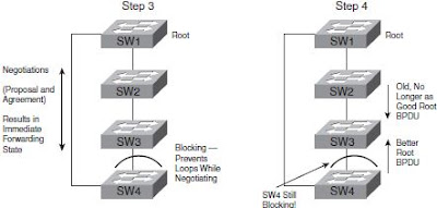
RSTP improves convergence over full-duplex links between switches—the links that RSTP calls “link-type point-to-point.” The first improvement made by RSTP over these types of links relates to how STP uses MaxAge. STP requires that a switch that no longer receives root BPDUs in its root port must wait for MaxAge seconds before starting convergence. MaxAge defaults to 20 seconds. RSTP recognizes the loss of the path to the root bridge, through the root port, in 3 times the Hello timer, or 6 seconds with a default Hello timer value of 2 seconds.


On Cisco switches, the STP cost is based on the actual speed of the interface, so if an interface negotiates to use a lower speed, the default STP cost reflects that lower speed per Table 2-6. If the interface negotiates to use a different speed, the switch dynamically changes the STP port cost as well.
Determining the Root Port on Nonroot Switches
Step 1 Determine all possible paths over which a frame, sent by the nonroot switch, can reach the root switch.
Step 2 For each possible path in Step 1, add the costs of all outgoing interfaces in that path.
Step 3 The lowest cost found is the cost to reach the root, and the outgoing interface is that switch’s RP.
Step 4 If the cost ties, use the port priority tiebreaker, and if that ties, use the lowest port number tiebreaker.
Determining the Designated Port on Each LAN Segment
Step 1 For switches connected to the same LAN segment, the switch with the lowest cost to reach the root is the DP on that segment.
Step 2 In case of a tie, among the switches that tied on cost, the switch with the lowest BID becomes the DP.
No comments:
Post a Comment